|
Motore di ricerca datesheet componenti elettronici |
|
|
Motore di ricerca datesheet componenti elettronici |
|
CC1010-RTY1 Scheda tecnica(PDF) 126 Page - Texas Instruments |
|
|
|
|||||||||||||||||||||||||||||
CC1010-RTY1 Scheda tecnica(HTML) 126 Page - Texas Instruments |
|
|
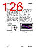
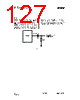
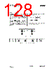
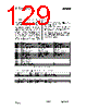
126 / 152 page  CC1010 SWRS047 Page 126 of 152 17.20 RSSI Output CC1010 has a built-in RSSI (Received Signal Strength Indicator) giving an analog output signal at the AD2(RSSI/IF) pin. RSSI is enabled when setting FREND.RSSI (see page 119). The output current of this pin is then inversely proportional to the input signal level. The output should be terminated in a resistor to convert the current output into a voltage. A capacitor is used to low-pass filter the signal. The RSSI voltage range is from 0 – 1.2 V when using a 27 k Ω terminating resistor, giving approximately 50 dB/V. This RSSI voltage can be measured by the on-chip A/D converter using the AD2 input. Note that a higher voltage means a lower input signal. The RSSI measures the power referred to the RF_IN pin. The input power can be calculated using the following equations: P = -48.8 VRSSI– 57.2 [dBm] at 433 MHz P = -46.9 VRSSI– 53.9 [dBm] at 868 MHz The external network for RSSI operation is shown in Figure 41. R281 = 27 k Ω, C281 = 1nF. A typical plot of RSSI voltage as function of input power is shown in Figure 42. When using the on-chip A/D converter, set ADCON = 0x06 to initiate a single conversion using VDD as reference. The converted RSSI voltage can then be read from the ADDATH and ADDATL registers. CC1010 AD2 (RSSI/IF) C281 R281 Figure 41. RSSI circuit 0 0,1 0,2 0,3 0,4 0,5 0,6 0,7 0,8 0,9 1 1,1 1,2 1,3 -105 -100 -95 -90 -85 -80 -75 -70 -65 -60 -55 -50 dBm 433Mhz 868Mhz Figure 42. Typical RSSI voltage vs. input power |
|
Link URL |
| Lei ha avuto il aiuto da alldatasheet? [ DONATE ] |
Di alldatasheet | Richest di pubblicita | contatti | Privacy Policy | Collegamento alla scheda tecnica | scambio Link | Ricerca produttore All Rights Reserved©Alldatasheet.com |
| Russian : Alldatasheetru.com | Korean : Alldatasheet.co.kr | Spanish : Alldatasheet.es | French : Alldatasheet.fr | Italian : Alldatasheetit.com Portuguese : Alldatasheetpt.com | Polish : Alldatasheet.pl | Vietnamese : Alldatasheet.vn Indian : Alldatasheet.in | Mexican : Alldatasheet.com.mx | British : Alldatasheet.co.uk | New Zealand : Alldatasheet.co.nz |
|
Family Site : ic2ic.com |
icmetro.com |
 Italian ▼
 English
 Chinese
 German
 Japanese
 Russian
 Korean
 Spanish
 French
 Italian
 Portuguese
 Polish
 Vietnamese
 Indian
 Mexican
 British
 New Zealand