|
Motore di ricerca datesheet componenti elettronici |
|
|
Motore di ricerca datesheet componenti elettronici |
|
ISL85415DEMO2Z Scheda tecnica(PDF) 20 Page - Renesas Technology Corp |
|
|
|||||||||||||||||||||||||||||
ISL85415DEMO2Z Scheda tecnica(HTML) 20 Page - Renesas Technology Corp |
|
|
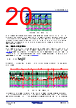
20 / 31 page  ISL85415 5. Detailed Description FN8373 Rev.5.01 Page 20 of 30 Jun.4.20 Output voltage is regulated as the error amplifier varies VCOMP and therefore the output inductor current. The error amplifier is a trans-conductance type and its output (COMP) is terminated with a series RC network to GND. This termination is internal (150k/54pF) if the COMP pin is tied to VCC. Additionally, the trans-conductance for COMP = VCC is 50µs vs 220µs for external RC connection. Its non-inverting input is internally connected to a 600mV reference voltage and its inverting input is connected to the output voltage via the FB pin and its associated divider network. 5.5 Light Load Operation At light loads, converter efficiency can be improved by enabling variable frequency operation (PFM). Connecting the SYNC pin to GND allows the controller to choose such operation automatically when the load current is low. Figures 58 shows the DCM operation. The ISL85415 enters the DCM mode of operation when eight consecutive cycles of inductor current crossing zero are detected. This event corresponds to a load current equal to 1/2 the peak-to-peak inductor ripple current and set by Equation 2: where D = duty cycle, fSW = switching frequency, L = inductor value, IOUT = output loading current, VOUT = and output voltage. While operating in PFM mode, the regulator controls the output voltage with a simple comparator and pulsed FET current. A comparator signals the point at which FB is equal to the 600mV reference at which time the regulator begins providing pulses of current until FB is moved above the 600mV reference by 1%. The current pulses are Figure 57. PWM Operation Waveforms Figure 58. DCM Mode Operation Waveforms VCOMP VCSA Duty Cycle IL VOUT IOUT VOUT 1D – 2LfSW ---------------------------------- = (EQ. 2) Clock IL VOUT 0 8 Cycles PWM DCM PWM Load Current Pulse Skip DCM |
|
Link URL |
| Lei ha avuto il aiuto da alldatasheet? [ DONATE ] |
Di alldatasheet | Richest di pubblicita | contatti | Privacy Policy | Collegamento alla scheda tecnica | scambio Link | Ricerca produttore All Rights Reserved©Alldatasheet.com |
| Russian : Alldatasheetru.com | Korean : Alldatasheet.co.kr | Spanish : Alldatasheet.es | French : Alldatasheet.fr | Italian : Alldatasheetit.com Portuguese : Alldatasheetpt.com | Polish : Alldatasheet.pl | Vietnamese : Alldatasheet.vn Indian : Alldatasheet.in | Mexican : Alldatasheet.com.mx | British : Alldatasheet.co.uk | New Zealand : Alldatasheet.co.nz |
|
Family Site : ic2ic.com |
icmetro.com |
 Italian ▼
 English
 Chinese
 German
 Japanese
 Russian
 Korean
 Spanish
 French
 Italian
 Portuguese
 Polish
 Vietnamese
 Indian
 Mexican
 British
 New Zealand