|
Motore di ricerca datesheet componenti elettronici |
|
|
Motore di ricerca datesheet componenti elettronici |
|
L9965P Scheda tecnica(PDF) 14 Page - STMicroelectronics |
|
|
|||||||||||||||||||||||||||||
L9965P Scheda tecnica(HTML) 14 Page - STMicroelectronics |
|
|
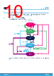
14 / 104 page  3.3 Power supply section 3.3.1 Main supply (ERBST) The ERBST pin is the main supply. This line: • Feeds the internal VANA LDO used for biasing the analog circuitry. • Feeds the internal VDIG LDO used for biasing the digital circuitry. • Feeds the internal VSTBY LDO used for biasing the circuitry in DEEP-SLEEP. The boost regulator is disabled by default and can be enabled via NVM setting the ERBST_EN bit to 1. Once the boost regulator is enabled via NVM, it can be turned-off via the ERBST_DIS bit. Once VERBST > VVBATMON - VERBST_DIS for t > tERBST_READY_FLT, the initial charge phase is over, the ERBST_RDY bit in the ERBOOST register is set to 1 and the switching operation starts. This ensures the presence of the external diode between VBATMON pin and ERBST pin. If VERBST < VVBATMON - VERBST_DIS after tERBST_READY_FLT, the ERBST regulator is turned-off and the ERBST_RDY bit is set to 0. Once started, the boost operates according to a bang-bang strategy, as shown in the Figure 4: • The controller is enabled and boosts the battery voltage whenever VERBST falls below the VER_WKUP_THX voltage programmed in the VER_WKUP_TH bit field for an interval longer than tER_WKUP_FLT. While in the duty phase, the IC is kept in NORMAL and any transition to DEEP-SLEEP is delayed until the setpoint has been reached. • The controller is disabled whenever VERBST reaches the target VERBST_XXX setpoint. This strategy guarantees high energy efficiency meantime the ER cap voltage is always charged for firing the pyro-fuse. In fact, considering the typical range for CERBST capacitor, the boost controller spends most of the time in the disabled state. Figure 4. ERBST controller working principle ERBST BOOST CTRL ERBST_EN DISA BLED ENABLED DISABLED ENABLED DISABLED tER_WKUP_FIL VERBST_FOR_min tERBST_STARTUP 0.9VERBST_XXX tDISCHARGE VERBST_XXX VER_WKUP_THX tCHARGE ΔVDISCHARGE To allow quick charging of the ER cap at every system startup, the boost controller has been designed to guarantee a maximum tERBST_STARTUP startup time in the worst-case application scenario. Moreover, the controller has been designed to limit the maximum power consumption to PIN_ERBST. It is possible to enable this function through the PIN_LIMIT bit in NVM. Note: In applications where the power limitation is required, to limit the initial inrush current it is possible to mount the resistor RCHG between the VBATMON pin and the ERBST inductor LERBST. Once the initial charge phase has finished (VERBST > VVBATMON - VERBST_DIS), the ERBST_RDY bit is set to 1. The MCU can read this flag and drive a GPIO to short the resistor RCHG. It is possible to kept disabled the ERBST regulator setting ERBST_DIS=1 in the ERBOOST register. L9965P Functional description DS14702 - Rev 4 page 14/104 |
|
Link URL |
| Lei ha avuto il aiuto da alldatasheet? [ DONATE ] |
Di alldatasheet | Richest di pubblicita | contatti | Privacy Policy | Collegamento alla scheda tecnica | scambio Link | Ricerca produttore All Rights Reserved©Alldatasheet.com |
| Russian : Alldatasheetru.com | Korean : Alldatasheet.co.kr | Spanish : Alldatasheet.es | French : Alldatasheet.fr | Italian : Alldatasheetit.com Portuguese : Alldatasheetpt.com | Polish : Alldatasheet.pl | Vietnamese : Alldatasheet.vn Indian : Alldatasheet.in | Mexican : Alldatasheet.com.mx | British : Alldatasheet.co.uk | New Zealand : Alldatasheet.co.nz |
|
Family Site : ic2ic.com |
icmetro.com |
 Italian ▼
 English
 Chinese
 German
 Japanese
 Russian
 Korean
 Spanish
 French
 Italian
 Portuguese
 Polish
 Vietnamese
 Indian
 Mexican
 British
 New Zealand