|
Motore di ricerca datesheet componenti elettronici |
|
|
Motore di ricerca datesheet componenti elettronici |
|
7480 Scheda tecnica(PDF) 33 Page - Renesas Technology Corp |
|
|
|||||||||||||||||||||||||||||
7480 Scheda tecnica(HTML) 33 Page - Renesas Technology Corp |
|
|
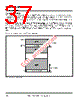
33 / 337 page  7480 Group and 7481 Group User's Manual 1-16 HARDWARE States of the CPU internal registers immediately after system is released from reset are as follows: • The interrupt disable flag (I) of the processor status register (PS) is set to ‘1’. • The high-order 8 bits (PCH) of the program counter contain the contents of address ‘FFFF16’, and the low- order 8 bits (PCL) contain the contents of address ‘FFFE16’. Since the contents of the CPU internal registers not mentioned above are undefined immediately after system is released from reset, it is necessary to initialize these registers by software. 1.7.1 Accumulator (A) The accumulator is an 8-bit register. Data manipulations, such as arithmetic or logical operation and transfers, are performed using this register. 1.7.2 Index Register X (X) Index register X is an 8-bit register that performs addressing in the index addressing mode. 1.7.3 Index Register Y (Y) Index register Y is an 8-bit register that performs addressing for certain instructions in the index addressing mode. 1.7.4 Stack Pointer (S) The stack pointer is an 8-bit register. It indicates the start address of the stack area where the contents of registers pushed at subroutine call or interrupt are stored. The low-order 8 bits in the stack are addressed by the stack pointer, and the high-order 8 bits are addressed by the content of the stack page selection bit. When this bit is ‘0’, the high-order 8 bits indicate ‘0016’, and when ‘1’, they indicate ‘0116’. For the 7480 Group and 7481 Group, the stack page selection bit is assigned to bit 2 of the CPU mode register (address 00FB16). Set this bit to ‘1’ if necessary, because it is cleared to ‘0’ at reset. Note: In the 7480 Group and 7481 Group, however, the product with RAM whose memory size is 192 bytes or less does not have RAM on 1 page. Therefore, clear this bit to ‘0’. Figure 1.7.2 shows the operation for pushing onto and pulling from the stack. Push the contents of necessary registers other than those described here onto stack by software. Table 1.7.1 lists the push and pull instructions for the accumulator and the processor status register. Initialize the stack pointer by software because it is undefined immediately after system is released from reset. Table 1.7.1 Push and Pull Instructions for Accumulator and Processor Status Register 1.7 Central Processing Unit (CPU) Accumulator Processor Status Register Push Instructions PHA PHP Pull Instructions PLA PLP |
|
Link URL |
| Lei ha avuto il aiuto da alldatasheet? [ DONATE ] |
Di alldatasheet | Richest di pubblicita | contatti | Privacy Policy | Collegamento alla scheda tecnica | scambio Link | Ricerca produttore All Rights Reserved©Alldatasheet.com |
| Russian : Alldatasheetru.com | Korean : Alldatasheet.co.kr | Spanish : Alldatasheet.es | French : Alldatasheet.fr | Italian : Alldatasheetit.com Portuguese : Alldatasheetpt.com | Polish : Alldatasheet.pl | Vietnamese : Alldatasheet.vn Indian : Alldatasheet.in | Mexican : Alldatasheet.com.mx | British : Alldatasheet.co.uk | New Zealand : Alldatasheet.co.nz |
|
Family Site : ic2ic.com |
icmetro.com |
 Italian ▼
 English
 Chinese
 German
 Japanese
 Russian
 Korean
 Spanish
 French
 Italian
 Portuguese
 Polish
 Vietnamese
 Indian
 Mexican
 British
 New Zealand