|
Motore di ricerca datesheet componenti elettronici |
|
|
Motore di ricerca datesheet componenti elettronici |
|
F4MP Scheda tecnica(PDF) 11 Page - NXP Semiconductors |
|
|
|||||||||||||||||||||||||||||
F4MP Scheda tecnica(HTML) 11 Page - NXP Semiconductors |
|
|
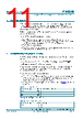
11 / 37 page  PTN3355 All information provided in this document is subject to legal disclaimers. © NXP Semiconductors N.V. 2016. All rights reserved. Product data sheet Rev. 3.1 — 4 November 2016 11 of 37 NXP Semiconductors PTN3355 Low power DP to VGA adapter with integrated 1 : 2 VGA switch 8. Power-up and reset PTN3355 has built-in power-on reset circuitry which automatically sequences the part through reset and initialization. In addition, there is a dedicated pin (RST_N) to control/effect reset operation externally. This provides flexibility at the platform level for debug or application purpose. Before link is established, the PTN3355 holds VSYNC and HSYNC signals LOW and blanks the RGB signals. While the PTN3355 performs power-on initialization, • The HPD signal is driven LOW, to indicate to the DisplayPort source that the PTN3355 is not ready for AUX channel communication. Once the device is initialized, the HPD level is produced based on CFG1_SCL/CFG2_SDA setting • The RGB outputs are disabled • The VSYNC and HSYNC outputs are maintained LOW as long as there is no active video streaming from the DisplayPort source. 9. Configurability and programmability The PTN3355 delivers flexibility for application usage by providing configurability via two options: • Configuration pins CFG1_SCL, CFG2_SDA, CFG5, DOCK_IN and TESTMODE • DP-AUX vendor-specific configuration registers The pins provide limited application board level configurability, whereas vendor-specific configuration registers deliver ultimate flexibility. The configuration pin changes (static, dynamic) are reflected in the IC behavior. The configuration pin definitions are as follows: • CFG1_SCL, CFG2_SDA are used for either host I2C communication or as dedicated configuration pins with binary leveled I/O. PTN3355 is flexible to accept either. The use of these configuration pins is defined in Table 8. • Configuration pin CFG5 selects OSC_IN clock frequency setting. Table 5 captures the pin definition. Table 6 captures DOCK_IN pin definition. Table 5. CFG5 pin definition Configuration input OSC_IN clock frequency setting LOW 25 MHz HIGH 33 MHz open 27 MHz Table 6. DOCK_IN pin definitions Configuration input VGA active output LOW channel 1 HIGH channel 2 |
|
Link URL |
| Lei ha avuto il aiuto da alldatasheet? [ DONATE ] |
Di alldatasheet | Richest di pubblicita | contatti | Privacy Policy | Collegamento alla scheda tecnica | scambio Link | Ricerca produttore All Rights Reserved©Alldatasheet.com |
| Russian : Alldatasheetru.com | Korean : Alldatasheet.co.kr | Spanish : Alldatasheet.es | French : Alldatasheet.fr | Italian : Alldatasheetit.com Portuguese : Alldatasheetpt.com | Polish : Alldatasheet.pl | Vietnamese : Alldatasheet.vn Indian : Alldatasheet.in | Mexican : Alldatasheet.com.mx | British : Alldatasheet.co.uk | New Zealand : Alldatasheet.co.nz |
|
Family Site : ic2ic.com |
icmetro.com |
 Italian ▼
 English
 Chinese
 German
 Japanese
 Russian
 Korean
 Spanish
 French
 Italian
 Portuguese
 Polish
 Vietnamese
 Indian
 Mexican
 British
 New Zealand